
Many years ago I went to look at a pre-estate sale in which an old machinist was selling his home shop machinery. I didn't buy anything that day but I remember being amazed at how smoothly his machines ran, especially his drill press. He told me "it takes a lot to make them run like that". The machine ran smooth as silk. I didn't question him further on what he'd done to make his machines run like that and have regretted it since. Anyway I've been idly looking for a drill press to try out my ideas on. I already have one which is a great machine made by Alzmetall but it has a 2MT spindle and doesn't go very slow.
After keeping an eye on local machinery ads for quite a long time. I finally found a shop looking to unload an older Taiwanese 20" drill press with 3MT spindle, for an excellent price. I bought it with the idea that I was going to try to do what that old machinist did to his machines - go through everything and make everything work perfectly, and try to make it run smoothly. Also, I had long suspected that most of the import machines were pretty much the same. I see guys looking for parts and have long wondered if parts from Jet or Grizzly would work.
Here's what I discovered after the initial examination:
The holes in the hub where the ball handles are screwed in were stripped out badly. One ball handle fell right out, another was barely engaged enough to not fall out, and the third had very loose sloppy threads that wouldn't tighten properly.
The table height adjust mechanism didn't work right. It barely worked at all. The table has a clamp and when you loosen it the table should freely rotate around the column and should crank up and down easily. Mine did neither.
The machine vibrated horribly. The vibration shook the whole machine.
The column was oxidized.
The table and the machined top of the drill press base were both badly discolored and in need of cleaning.
The machine's power cord was cheap, stiff, and way too short. Unplugged, hanging straight down from the drill press head, it barely reached the floor.
On the other hand, everything was there. The belt guard opened and closed correctly and wasn't dented. And I like the general design of this type of drill press. I like the table height adjust/swivel mechanism, the wide speed range and the integral work light. Also, it's a 20" drill press with tee slots on the table and base. All in all, it seemed like a good candidate for restoration.
The machine looks like a clone of a Jet JDP-20MF drill press. It's branded "Foremost". I used to see Foremost machines at Tool Town stores in the Seattle area. Foremost was an importer based (I believe) in western Washington state just like Jet and Grizzly still are today. There were several smaller importers in those days ('80s and '90s) with brands like Union Tool or Orbit. To my eye, those machines were made quite a bit better than similar looking machines sold today (at much higher prices).
So that's how things were when I got this machine home in November of 2015. This little page is a description of the things I did to the machine to improve it from its as-bought condition. Sadly, I didn't take a lot of photos in the beginning. I figured most everyone knows what a junky old drill press looks like. So the first things I did I'll just describe in text.
I started by cleaning the machined surfaces on the table and base casting. I used kerosene and a random orbital sander with a 5" round brown 3M pad. I don't know if there's a better fluid, but kerosene seems to work fine so I keep using it on my projects. The machined surfaces cleaned up pretty well. Dip a brush in a can of kerosene, brush it on the table, scrub with the random orbital sander, wipe away black liquid with a rag, repeat as needed. It was gratifying to see the original grinding marks emerge!
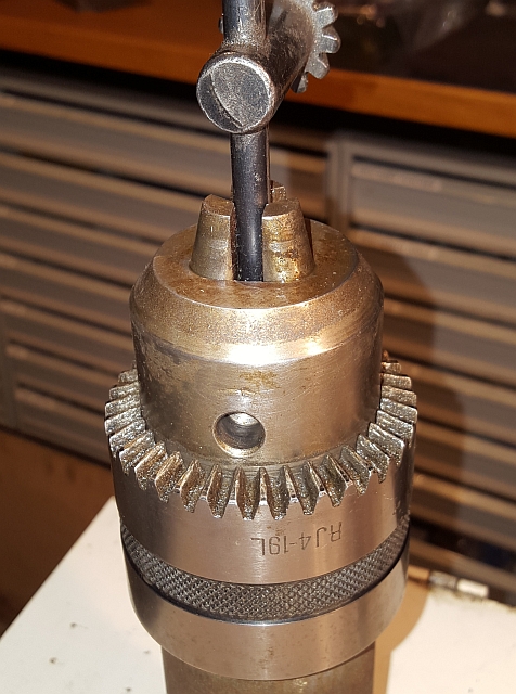
Next I turned my attention to the actual machine itself. I took the 3MT drift pin that came with the machine and started to remove the drill chuck from the spindle. Woops, the drift pin was all boogered up. Don't know how it got so abused, but I've seen much stranger things happen in a machine shop. Anyway, I dressed the mushroomed and malformed drift pin until it worked smoothly and resolved to buy a better quality 3 Morse taper drift pin someday. With the drill chuck removed, I was happy to see that the spindle taper was in perfect shape and had very little runout. I know that the importers kept prices low in part by using very cheap drill chucks, so I decided that this machine would get a much higher quality chuck. Here's what the old chuck looked like:
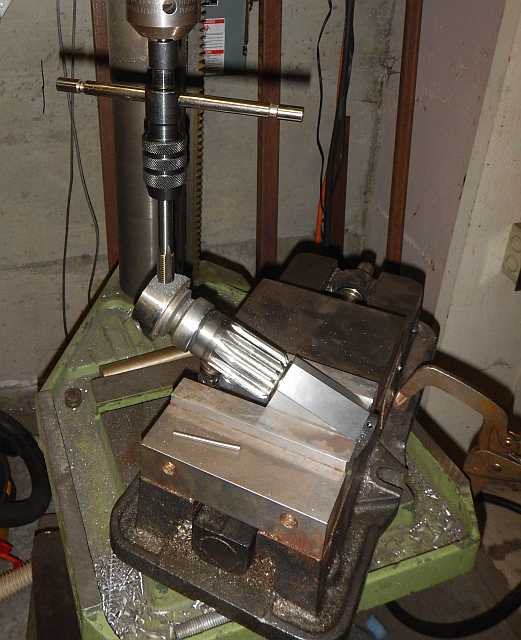
Next I removed the spindle and feed shaft assembly, following the procedure I saw in a video online which showed the disassembly/reassembly procedures. With the feed shaft assembly out of the machine, I measured the handle angle. I put the feed shaft into a hex-shaped 5C collet block. I clamped a mill vise to the table of my (working) drill press so I could drill out the stripped holes.

I drilled and tapped all 3 holes for 1/2-13 threaded inserts:
The ball handles themselves were in good mechanical condition but the finish on them looked cheesy, like a bad chrome plating job. I spun each handle up in the lathe and polished with a brown 3M pad and the handles came out looking like slightly brushed stainless. I thought there was a cosmetic improvement. Encouraged, I also polished the hub and got a similar improvement. The ball handles screwed in solidly and the whole thing looked 100% better. Have a look:

With the problem of the stripped out ball handles solved, I took a look at the pulleys on top of the head. There are 3 step pulleys yielding a very usable speed range of 150-4200 rpm. I checked the pulley alignment. It wasn't too bad, but it turned that the hole for the idler pulley swivel arm was bored just a bit off of vertical. I decided to ignore the problem for now. I removed the belts and motor and removed the head from the column.
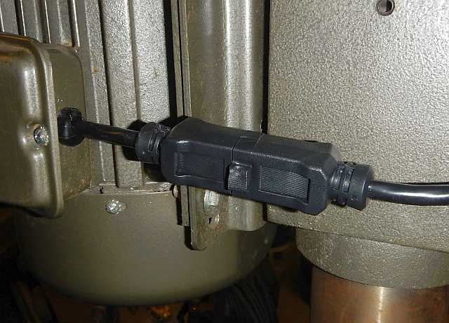
Removing the drill press motor was somewhat of a PITA because of the motor wiring. I went into the motor's junction box and disconnected the power cable, and then removed the strain relief fitting to remove the cable. Then the motor came off easily. I decided to install a quick disconnect on the motor wiring. I cut the ends off a cheap extension cord and wired them in place of the motor's power cable. Now it's easy to disconnect the motor's wiring:
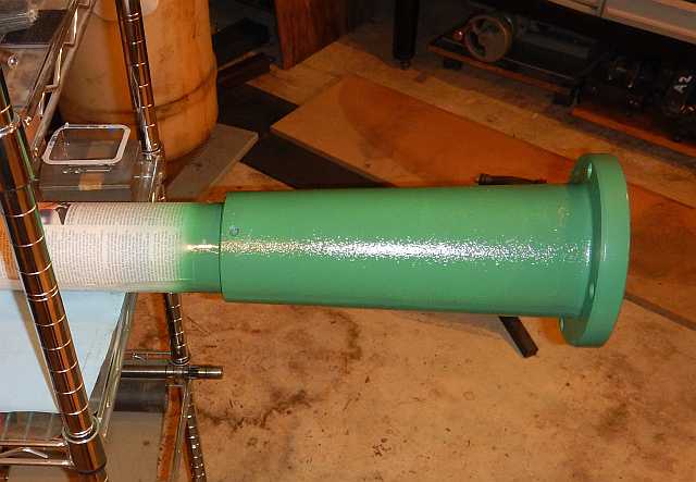
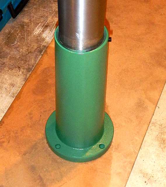
After I removed the head, I removed the table and its height adjust mechanism. I also unbolted the column foot casting from the drill press base casting. There being no practical way to get the column out of its foot casting, I chucked up the column with the foot casting still on it. I used the steady rest on my lathe and spun the column up and polished it. The steady rest left marks that you can see if you look just right, but the column polished up nicely. I applied Boeshield T-9 to the column and to the cleaned machined surfaces of the table and base casting.
Then I examined the height adjust mechanism. I discovered both the worm and the pinion were badly worn. I downloaded the manual for the equivalent Jet machine and decided to order parts for that machine and see if they fit my machine. The new parts fit perfectly and the table raised and lowered a whole lot better. The rack's ends needed a bit of handwork, so I dressed them with a file. After I lubricated the area, the table swiveled around the column much better than it had when I got the machine. Here's a link to an exploded parts diagram for a Jet JDP-20MF, the machine that's close enough to mine so the parts fit:
With everything apart I started cleaning, masking and painting. Here are a few pictures:


While I was waiting for the paint to dry to full hardness I checked out the motor. I removed the pulley and spun up the motor on the bench. It ran with a loud whine and walked around on the table under its own power. So I decided to fix that next.
Faced with a cheap 1 horsepower single phase drill press motor, the first thing I considered was to replace it with a better quality motor. It isn't hard to find replacement motors, but they come with a price and no guarantee they wouldn't run smoothly either. I decided if I were going to spend that kind of money, I'd rather get the rotor balanced. I tore the motor down and took the rotor to the balancing shop. I also brought the centrifugal switch, the fan blade and the step pulley, since all of these had to be balanced along with the rotor. I used Balancing Services Company in south Seattle and was very glad I did. They let me into their shop to watch, as they did a thoroughly pro job of dynamically balancing the rotor. First they balanced the rotor by itself (it was way out, amazingly bad) and then they balanced it with everything attached. To be quantitative, the rotor started out with 0.5 oz-in imbalance and they balanced it until it was within 0.01 oz-in. So the imbalance was reduced by a factor of 50!. Incidentally, they didn't remove any metal. Rather, they used a 2-part epoxy putty to add weight as needed. Here's what the rotor looked like after balancing:

Here is a picture of what my rotor looked like on an IRD Mechanalysis balancer in Balancing Services Company's shop:

Here's a picture of that balancer zoomed out a little. Interesting machines - the rotor sits on 4 wheels which can be adjusted to accommodate different shaft diameters at each end. There is a flat belt over the rotor which is driven from below by a DC motor in a servo loop for very precise speed control. There is a laser aimed at a shiny piece of metallic tape to measure RPM and there are two accelerometers, one under each bearing, which measure the magnitude of the oscillations. With the laser putting out a square wave at the exact spin frequency, it is possible to measure the phase angle of the oscillation as well. I found the whole process fascinating.

If you're curious about how oscillating parts can run on solid bearings, look at the next graphic, which shows that the entire soft bearing assemblies are suspended gimbal-style:

Back at my shop, I installed new motor bearings (Nachi shielded bearings made in Japan) and reassembled the motor. When I spun it up on the table it ran much more quietly and there was no walking around. Many years ago I'd worked on a different drill press which also had a motor with very unbalance rotor. I cobbled up a pair of knife edges on a surface plate and did a static balancing job. The vibration decreased somewhat but it was nowhere near smooth. After this balancing experience I now believe that the very best solution for power tool electric motor vibration is dynamic two-plane balancing.
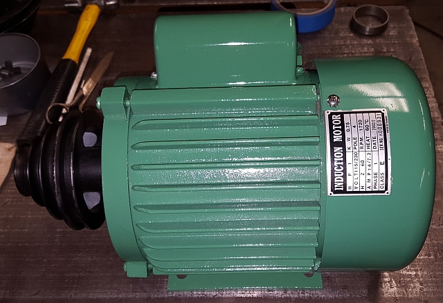
With the motor running smoothly, I installed the pulley. I wasn't happy with the way it attached to the motor shaft. It's set screw was supposed to press on the key, but it hit right on the very end of the key. It could have worked its way loose. I drilled and tapped the pulley in the center of the smallest vee groove. That put the set screw in the center of the key so the pulley couldn't come loose. Then I masked and painted the motor. Here's the restored motor:
The belt guard on this machine is made of very light gauge sheet metal. I was happy when I bought the machine because the belt guard wasn't dented and the hinges and spring latch were still in good shape. The effect of vibration on the belt guard was to make it act like a piano's sound board. It very efficiently turned machine vibration to sound. As it vibrated it also rattled quite badly. This was BEFORE I got the motor balanced. I had made plans to reinforce the lower side sheet metal by sistering it with 16 gauge sheet steel. However, I was delighted to find that all of the rattling disappeared once the motor was balanced!
The next step was to mask and paint the drill press head. I completely stripped the head casting. I cleaned it and masked it for painting. I like to cut out little bits of paper and roll them up loosely and let them unroll inside holes. This does a pretty good job of masking the inside of machined holes for painting. I thought I'd taken a picture of the head masked for painting, but I didn't, sorry!
I had to remove the spindle pulley assembly. There is a trick to removing the nut - it's got a left hand thread! On my machine a 1-3/8" wrench fit the nut fine, and it came right off once I got a grip on the pulley with a Vise-Grip chain wrench. The spindle pulley shaft is fitted with two large 6206 bearings along with a bearing spacer. It is retained in the head by two heavy spring clips. It was easy to remove the top one with needlenose pliers, but the bottom one took some head scratching. I eventually turned the head upside down so I could see the lower spring clip way down inside the head casting. I found a long pin that would fit into the gap in the spring clip and carefully tapped on the outer race on the lower bearing. This moved the (press fit) shaft/bearing assembly out far enough so I had about a 3/8" gap to work with. Then I put the same drift pin right onto the spring clip and gave it a whack with the hammer. It popped out of its groove right where I hit it. I worked around the clip, tapping on it just hard enough to free it completely from its retaining groove. Then I was able to turn the clip enough so that I could get in there and pull it out. After that it was easy to press out the shaft/bearing assembly. As a side note, a short length of 2" pipe is a good tool for removing 6206 bearings, since it's OD is just smaller than the bearing's but it's still large enough to bear solidly on the outer race.
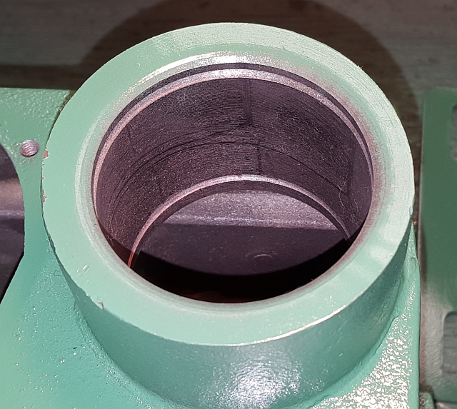
The bearings on the spindle pulley arbor were slightly sticky. They were shielded on one side and open on the other. I soaked them overnight in kerosene and worked them over and blew them out and regreased them. After cleaning and regreasing, they felt just like new, so I pressed them back onto the spindle pulley arbor with the spacer in between. The open sides are on the inside, where nothing to speak of can get in.
The next three pictures show the retaining ring grooves and the reinstallation of the spindle pulley arbor.


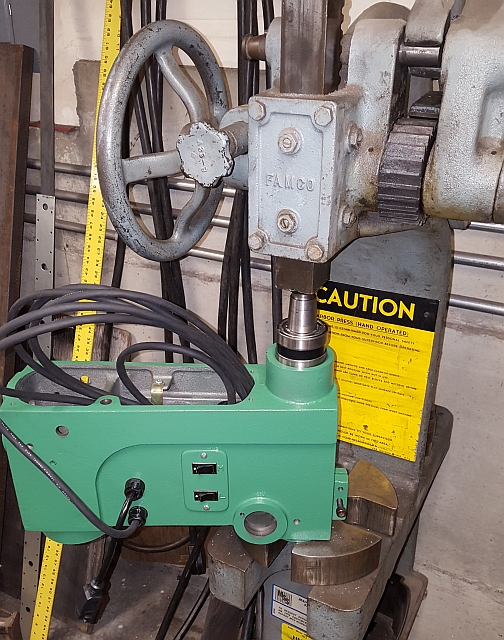
In the third picture above, the spindle pulley shaft has been pressed into the head and I'd already installed the retaining clip. I found the easiest way to install the retaining rings was to use my fingers. Anyway, I also took a picture when I pressed that shaft with its bearings into the head. The moral of the story in the next picture is when it comes to arbor presses, headroom RULES. The head casting and the spindle pulley arbor both fit under the ram. It never would have fit into my old two ton arbor press, that's for sure!
If you look closely at the picture just above, you can see the new power cord I installed, coiled up and stuck into the head casting to stay out of the way. I bought a 15' length of 14-3 SJOOW cable and an industrial 117 volt single phase 15 amp plug and made a new power cord. I used SJOOW instead of SO cable because it is much more flexible and also quite a bit smaller in outside diameter. I needed the small diameter to fit the original power cord's strain relief fittings. Along the way I tried to find where I could buy new strain relief fittings. I carefully measured the threads they screwed into and found they were just over 20mm and, amazingly, just about 18 tpi. What kind of weird thread is that? Well, it turns out it's a PG thread, which was new to me. I learned that a tight-fitting cord strain relief is more correctly called a cable gland. Anyway, in the end I decided to just use the old ones. The new cord is tight but it works.
With the work on the head completed, I put the head back onto the machine, then lubed and installed the quill assembly and the feed lever assembly and the clock spring. I tensioned the clock spring just tight enough to make it return fully. I put a 3MT-4JT shank into my Jacobs 18N and put that into the spindle.
One last note about vibration. I decided to try link belts instead of using rubber vee belts. Many guys have written that they seem to reduce vibration. Anyway, I bought one length from Harbor Freight and then bought another foot on ebay to get enough for both belts. I found them easy to take apart and put together, and they do seem to run just fine. There is a faint sound as the new belt segments hit the pulleys, but I think they will break in and that sound will diminish.
With the motor humming quietly and without the buzzing and rattling, I could hear noise coming from the spindle. The last thing I did was to tear down the quill assembly (pressing out the spindle and bearings). I cleaned the quill and spindle meticulously. The rack teeth cut in the spindle was full of chips. That should really be considered part of the machine, as chips and dust can enter through the arbor ejection slot in the side of the quill. I had noticed some slightly chunky action raising and lowering the quill. I thoroughly cleaned and regreased the thrust bearing, and replaced the small and big end spindle bearings. With the spindle now nice and quiet, this machine sounds nothing at all like an import drill press anymore!
Before I show you all the "after" pictures, I want to summarize. I fixed the stripped out holes in the hub where the ball handles screw in. I put Jet JDP20MF parts onto a Foremost 20" drill press and found them to fit correctly, restoring the rack and pinion table height adjustment to working order. I cleaned the oxidized and dirty machined surfaces of the column, table and base casting. I fitted the machine with a new power cord and rewired the motor's power cord so it is easy to take apart. I had the motor precision balanced and installed new bearings and moved the motor pulley's set screw. I put in a new longer and more flexible power cord. I replaced the chuck with a Jacobs 18N ball bearing chuck. I cleaned all the exterior parts and gave them a fresh coat of Rustoleum Machine Green. And, of course, I rebuilt the quill assembly with new spindle bearings.
This drill press now runs smoothly and quietly, with no rattles. It's got a quality chuck on it, and I think it works better than new. It certainly works better than the Jet JDP17MF I used to own. And I think it looks great! See what you think in the pics below.
Thanks for reading!

