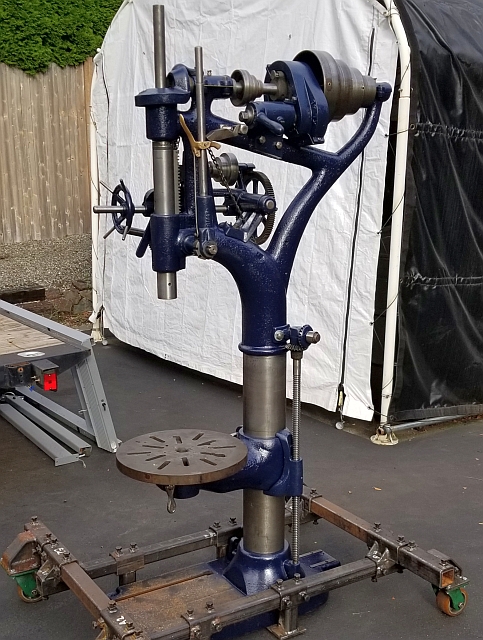
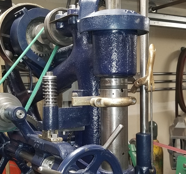
During the pandemic of 2020 I had quite a lot of time alone in my shop. One of the projects I filled my time with was restoring an old Canedy Otto no. 36 Power Drill, shown above nearly finished. I'm not going to write about the whole project here - this is just to describe my process of replacing the missing assembly that clamps onto the quill and sets the point at which the machine's powerfeed will stop. I call this assembly "stop collars". Mine were missing entirely. I gather this is often the case. The stop collars reduce quill travel by nearly an inch when installed, so many operators chose to remove them at which point they got lost.
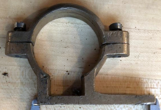
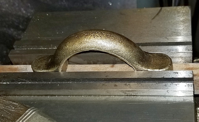
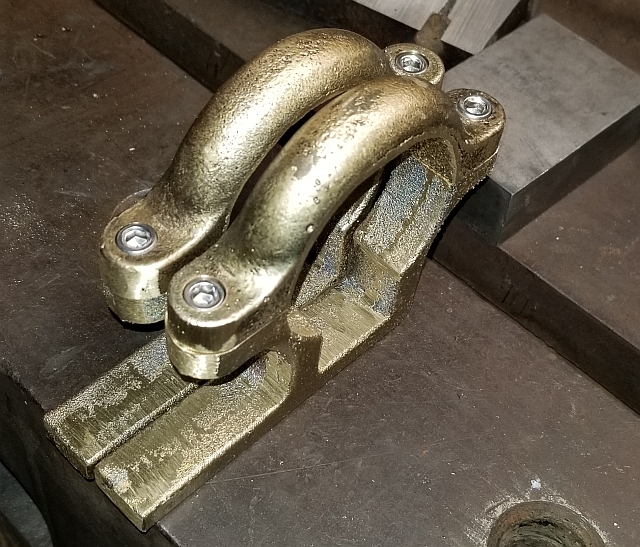
In doing my research into these stop collars, one helpful person send me detailed photographs including measurements. This picture is useful to see what the two halves of the assembly look like as well as roughly how big they are:
Since mine were missing entirely, my first inclination was to find some from an old machine being scrapped. I realized immediately that this was very unlikely. Parts for a machine this old are essentially unavailable. So I decided to make my own.
The first way I thought about was to fabricate the stop collars by a combination of cutting welding and machining. I'm sure this would have worked but the result would not look original. In particular, a fabricated set wouldn't be made of bronze. So I decided to have castings made and then machine them to fit each other and to fit the machine.
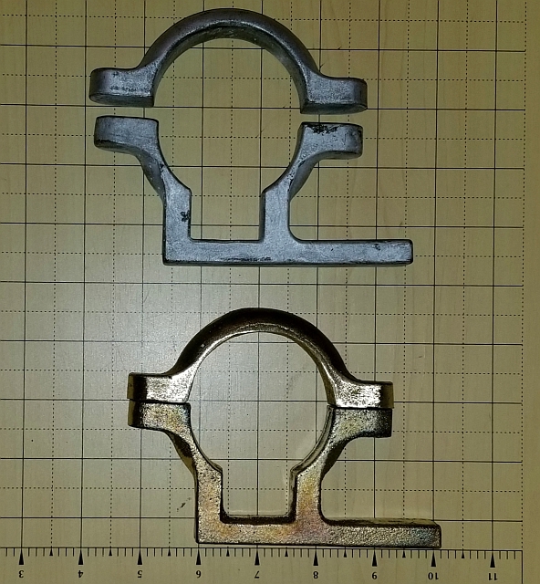
The first step in having castings made is to make patterns. These days there's no need to glue together hardwood bits to make a pattern. Simply draw it up in CAD and 3D print them. This is what I did. More accurately, I asked a (much younger and more current) friend to do the CAD and 3D printing work. Upon receipt of the pair of patterns I visited several foundries in south Seattle. I chose to have Gil's Aluminum pour my castings out of C95400 aluminum bronze. I had thought to have them cast from 85-5-5-5 red brass but the bronze is much stronger, plus they would be pouring bronze before brass and in fact didn't have any brass pourings scheduled so the wait could have been several months. The picture below shows one set of castings I received plus the patterns. The patterns look silver after being rammed up, but they were green when first printed.
Next I needed to machine them first to fit each other, then to clamp solidly on the drill press quill. I don't have much experience machining raw castings. I decided to document the process in case my experience might benefit someone else.
The rest of this page describes the machining. The cutting part is simple, nearly trivial - the real issue is workholding. The castings were fairly regular but had some lumps and slight irregularities. I cleaned those up with a file.
Before I start, let me define terms. I think of the two castings as being a top piece and a bottom piece. The bottom piece is the one with the protruding arm. In use, this arm contacts a lever which releases a spring and pops the power downfeed assembly out of engagement. The top piece is the smaller piece with two ears.
Before I got to the machining, I realized the top collar had not quite come out as designed. It was supposed to be 180 degrees, half of a hoop which fastens around a round piece. But it was sprung just a bit. So I put it in a big bench vise and just bent it back into shape. I did this carefully, worrying about breaking the casting. But it worked, and now the ears of both parts were the same length.
To machine the ears on the top casting, I started by putting a tee nut and stud into the middle tee slot of my mill table. Then I put a 123 block over the stud (the stud went through a hole in the block). I intended to hold the part down with a strap but when I put a strap on it didn't quite sit solidly. So I cut up 3 small pieces of copper shim and placed them on the part:
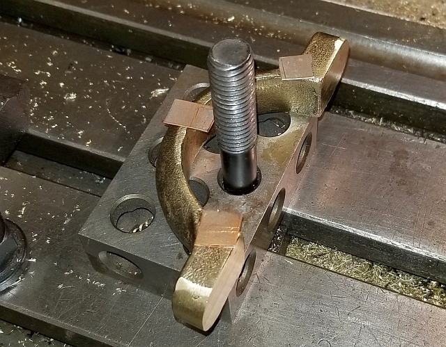
With the strap bearing on 3 places, it was solid. So I added the strap and a hold-down nut:
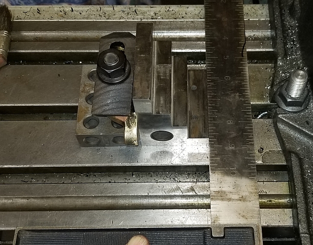
As you can see, the ears stick out past the edge of the block and also past the edge of the clamping strap. This allowed an end mill to face the ears off easily. I made sure the part was square to the X axis of the mill by setting the ears against a small angle plate. I used a large machinist square held against the front of the table to make sure the accurately ground angle plate was square. With the feet against the angle plate, that meant that they also were square, so I clamped the part solidly in that position:
After all that setup work, the actual facing cut was trivial. I ran an end mill past the ears until they were machined flat and parallel. This completed the facing operation on the top half.
Incidentally, I have a 2x72" belt grinder with a very flat platen. I could have just flattened the ears by holding each part against the belt. But I didn't think of that until it was too late. Anyway, the way pictured here worked fine.
I could have machined the ears on the bottom piece the same way, but I found an easier way. I put a piece of hardwood into the mill vise and set the arm of the bottom piece down on it and clamped it:
When I milled the ears flat, this assured they would be parallel to the long arm. Plus, I could machine the holes in the same setup. I used an edge finder to pick up both ends and used the 1/2 function on the DRO to find the center. I did the same thing on the (clamped) mill jaws to located the Y center of the part. I determined the holes needed to be 3.75" apart. With a DRO, it was easy to move to the correct location. I drilled and tapped the holes 1/4-20 and the facing and drilling operation on the bottom piece was done.
To do the drilling and counterboring operation on the top half, I used basically the same setup:
I again used the edge finder and DRO to locate the holes. I drilled 1/4" clearance holes right through the part into the hardwood block, then used a 3/8" end mill to plunge the counterbores.
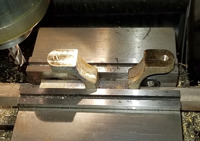
Here is a shot of the stop collars after the ears were faced, drilled, tapped, counterbored and assembled. (In fact I got 2 sets of stop collar castings and am machining them both. One will go to the owner of a different machine of the same model.)
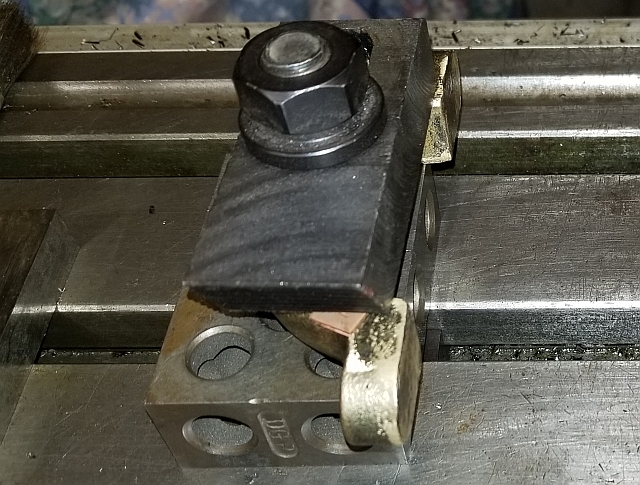
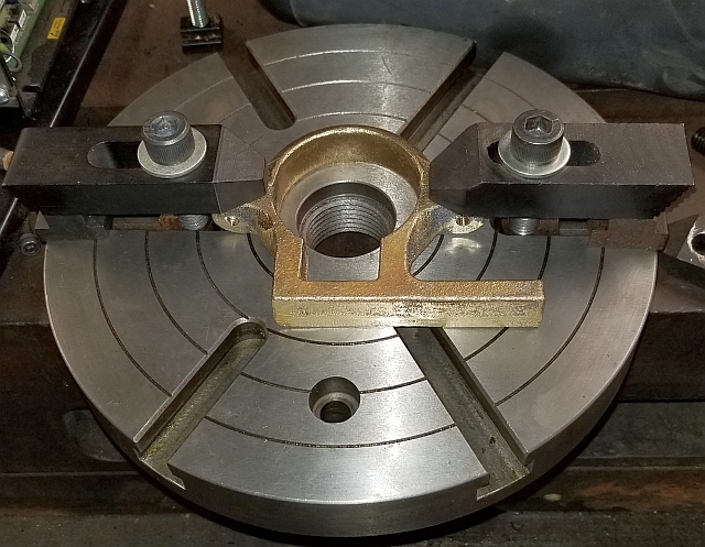
I thought about using a 4-jaw chuck to bore the central hole to fit the quill but in the end I decided to mill the hole using an indexing super spacer in rotary table mode. My spacer came with a faceplate. After some puzzling, I came up with this method of clamping the stop collar in place:
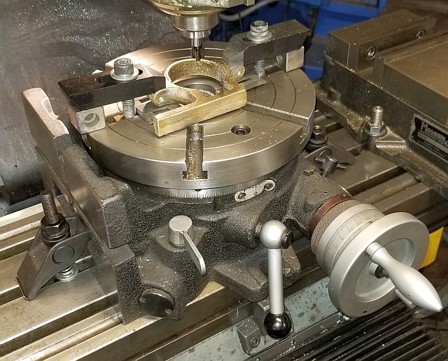
Let me digress for a moment. I don't have a big rotary table any more. I got an indexing super spacer recently and I use that instead. Mine is an 8" model made in Taiwan. It is well made and has worked perfectly for me each time I've used it. I did discover two tricks to using it: first, don't try to bolt it down to a Bridgeport table via its table slots! Instead, orient the table slots with the Y axis and use hold-down straps to clamp the spacer to the table. Second, remove the chuck or faceplate before you move it. Without the added weight, I can just manage it. It's easy to bolt them back on once it's on the mill table.
Anyway, once that was installed on the mill and centered, I clamped the part to the faceplate as shown above only using packing to get it up off the faceplate. With the part lightly clamped, I used the edge finder to tell me how centered the part, and just tapped it around until it was "good enough". Then with just a few minutes of milling time, the machining was done.
Here is the milling setup:
After all that, I was a bit nervous. I tried installing it on my quill and to my relief it bolted on and seemed just about right! I'll leave you with a picture of the stop collar installed on the quill. You can see how the yellow metal pretty much matches the squeeze lever on the quill feed lever.
Thanks for reading!