I generally work in my shop alone. Sometimes I need to move large heavy machine tools by myself. Dissatisfied with previous machine moving solutions, I built a new design that should work out much better. This little project Web page presents my current machinery moving solution, which I call the "modular tube dolly". It is based on pieces which slide over 2" square steel tube. It is made up of several subassemblies, so it is modular in nature. Assembled, it forms a single rigid dolly which holds a machine 3/4" above the floor while being on wheels so it can easily be moved by a single person.
The best solution for moving machines is to use a forklift. Forklifts are expensive, and old ones often don't run well. Their biggest drawback is their size, though. They take up as much space as a small car. In a small home shop this is completely unworkable.
Another commercial solution is Hilman-type machinery rollers. A set of rollers is very expensive. Guys have made them but the fabrication requires precision machining. If no milling machine is available it isn't practical to make a set of machinery rollers. Also, the machine tools have to be lifted several inches and put down onto the rollers, which must be positioned accurately. Any time you lift a machine more than an inch off the floor it makes me very nervous. And certainly it doesn't seem like one guy could use a set of machinery rollers by himself.
I have a good friend who uses and recommends pallet jacks for moving machinery. Pallet jacks are relatively inexpensive, but they have severe drawbacks. They cannot pick up your machine unless it is already on top of a pallet. Getting a heavy machine tool on or off of a pallet without a forklift can be quite challenging and certainly requires another machine to do the lifting. For example, you can use an automotive engine hoist to lift a machine onto a pallet. Now you not only have to store a pallet jack, but you also have to store an engine hoist. And, like a forklift, pallet jacks take up an inordinate amount of floor space.
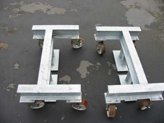
My previous solution was a shop-built pair of machinery skates.
This pair of skates were cheap. At the time I built them, the casters were about $10 each from cheapcasters.com now sadly no longer. The metal was all scrounged. I added these skates onto a galvanizing job which was paid for by a job I was doing. So all in all they were cheap. But they did have drawbacks.
The worst thing about them was that you had to tie them together with ratcheting straps, or one of the skates could easily slide out from under the machine being moved. Another issue is that they can only accept a machine of a maximum width. This makes you design your skates quite wide, so that they can accommodate the largest envisioned machine. They don't always work really well on smaller machines, however. Also, there isn't any good way to align the skates with each other. So you can wind up with a wider profile than is convenient. In addition, they are large and heavy and take up as much room as a fair sized welding table.
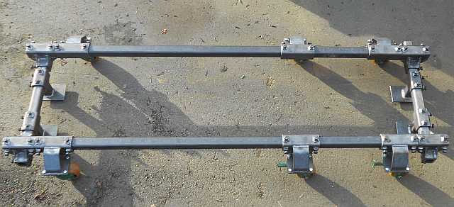
Eventually I sold my machinery skates to a university shop and started looking for a better solution. Awhile ago I ran into a forum posting which inspired me. On a recent 2-month car trip I had a lot of time to think about a design in my head. I drew up some plans when I got home and recently completed fabrication. Here is a picture of my modular tube dolly assembled with 6 casters. Note that the dolly is set up to move a 14x40" lathe whose headstock end is quite heavy. I bought my casters used and do not know the maker nor the weight rating. Assuming they can each hold 600 pounds, with two of these on each side of the headstock end it can handle a 2400 pound headstock. So I think I'm safe. At any rate, here's the pic:
Like my machinery skates, the dolly has a pair of fingers at each end which slip under the machine and hold it 3/4" above the floor. Unlike my skates, the casters on my dolly are mounted out to the side of the tube rail. See pic:
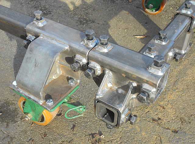
I designed my casters with an offset to keep the wheels from fouling on the machinery base as the casters swivel around during turns. It did mean that I had to build in a great deal of strength to withstand the forces involved. Not that I actually engineered anything - I just built it from 1/4" thick material and used gusseting to beef up the corners. The main outer gusset looked like it could crumple to me so I added an outer flange. The combination is a bit like an I-beam in the way it distributes forces. I think it looks good and should be very strong.
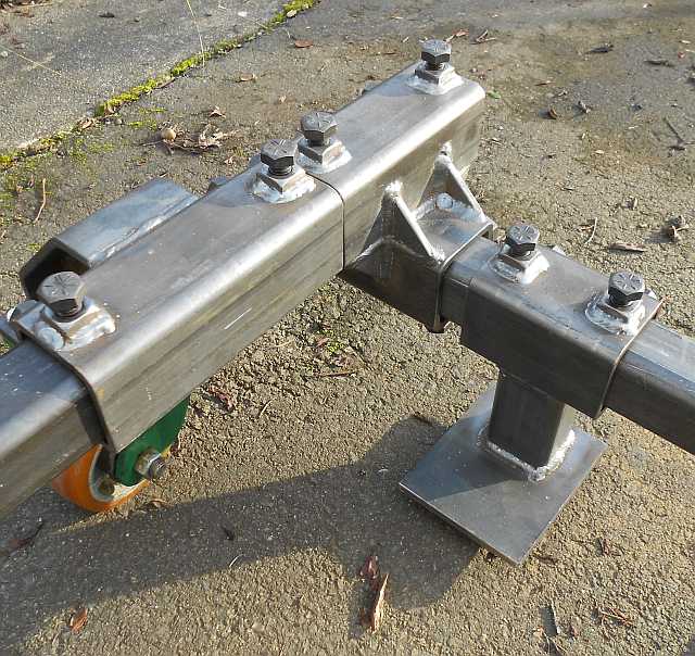
There are 3 types of fittings which slide over the tube rails. The first is the caster carriers which I have already described. The second type is the corner fitting. While it might have been strong enough just welding the two pieces of outer tube together at a 90� angle, I chose to add 8 gussets. It isn't easy to see where all 8 gussets go in the pictures. I have included a link to my shop drawing which may be clearer. The gussets stabilize and strengthen the corner fittings. The 3rd type of fitting I call the fingers. The finger design uses a 4x5x5/16" flat piece to slip under the edge of the machine and hold its weight. I couldn't use gussets so I am relying on the weld holding the finger plate to the vertical drop tube. These welds are critical. I have been welding for many years and trust my welds. If you decide to make a similar design make sure that the person who welds these joints knows what they are doing.
Here is another picture showing a corner from the inside, which lets you see the finger piece more clearly.
All 3 of these fittings use an outer tube which is cut from a 20' length of 2-1/2" receiver tube, used in the manufacture of trailer hitch receivers. If you stick to regular square steel tube it's hard to find tubes which nest well. Generally square tube has a weld flash on the inside which prevents it sliding easily over a nesting tube inside it. Trailer hitch receiver tube isn't 2-1/2" 1/4" wall tube. Rather, it's 2.53" square tube with 0.24" walls and the inside weld flash is removed. When you buy 2" square tube material the outside dimension will be very close to exactly two inches. There is about 1/16" slop between the outer tube and the inner, which is why it is easy to slide one over the other. My design uses pinch bolts to take up the slop and to hold all of the pieces firmly fastened together. With the pinch bolts loosened, the fittings slide easily over the tube rails. With the pinch bolts tightened, everything is held square and rigid. My modular tube dolly used just about half of one 20' length of receiver tube. I paid $135 for a stick of receiver tube in late 2014. My total material cost was just under $300. To get the whole cost I'd have to add the cost of welding wire and shielding gas but I don't have any way to easily quantify those costs. It's easy to see that even with all new tube and using grade 8 pinch bolts, the modular tube dolly is reasonably inexpensive to build.
A note on the casters I used: my casters have 4x2" wheels made of an aluminum core and polyethylene tires. The caster body is all 1/4" steel. The casters are fitted with swivel locks so they can effectively switch from swivel to rigid. As mentioned above, I don't know the weight rating but my best guess is about 600 pounds per caster. I paid about $10 each for these used, a good bargain.
My method of usage is simple. Configure the dolly with rails sized to fit the machine being moved. Separate the fingers on each end rail by enough space so you can get a large (five foot or more) pry bar between them. Leave one end rail off, and roll the remaining U-shaped piece around the machine so the fingers go right up next to the base. At the far end of the machine, put the end rail assembly onto the caster rails as far as it will go. Back at the other end, use a long pry bar to lift one side of the machine and roll the dolly under it, then lower the machine onto the fingers. Use a pair of wedges so the machine cannot roll in the direction of the mounted end. Then slide the end piece at the far end so its fingers touch the machine base. Use the long pry bar again at the far end to lift the machine, and slip the end piece's fingers under the machine as far as it will go. Tighten up the pinch bolts on the end piece and the machine is ready to move.
Following are pictures of my 14x40" Nardini lathe mounted on the modular tube dolly.
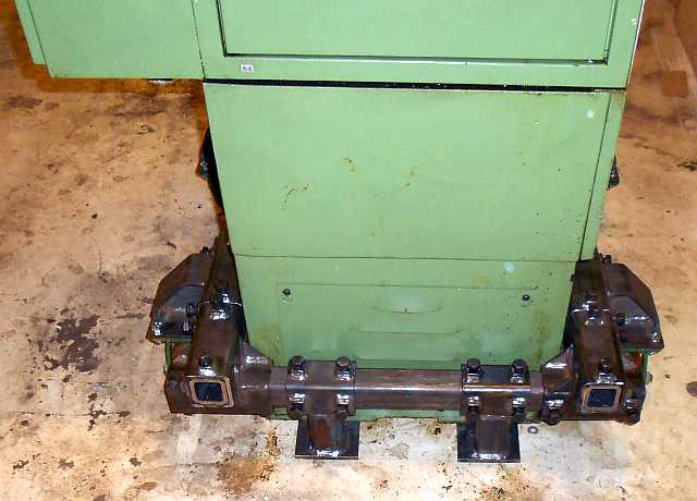
Headstock (heavy) end:
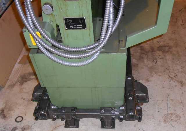
Tailstock (lighter) end:
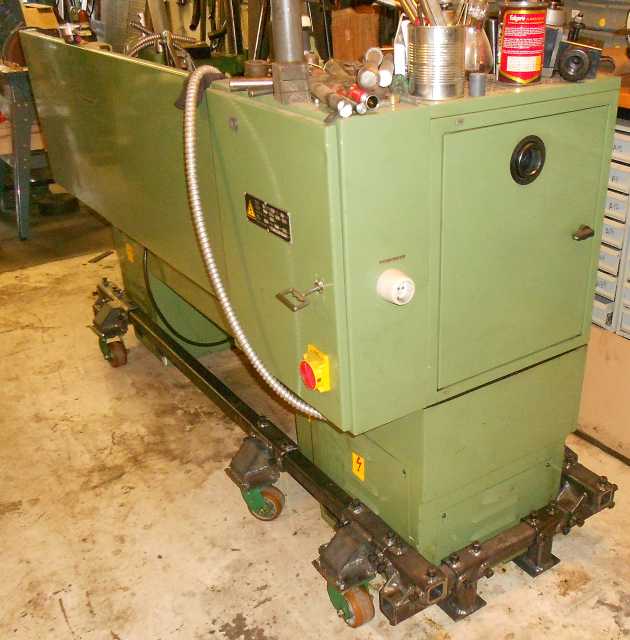
View of the whole machine with extra casters near the heavy end:
I can easily roll my lathe once mounted on my dolly. I'm pretty happy with how the modular tube dolly works. The best thing about it is that when I'm done using it I can put all of the fittings into a single box on a shelf, and lean the tube rails up in a corner. It occupies a small footprint. I enjoyed making it. I didn't do any precision machining in fabrication. I used a horizontal bandsaw, a small ironworker, a drill press, a mag drill, and a welder.
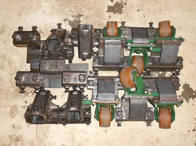
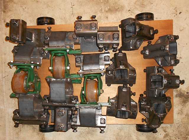
One last word: after moving my lathe as shown above, I took all of the dolly fittings off of the tubes, and leaned the tubes against the wall between two Kennedy rollaways. They are not in the way at all there. The fittings, though, required some rethinking. My original ideas of piling them in five gallon buckets or maybe putting them in a box on a shelf didn't really make sense when faced with the actual parts. They made quite a pile on the floor:
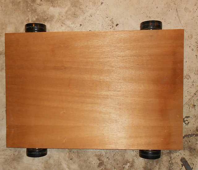
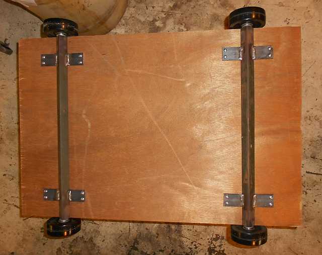
So I decided to make a "part cart" or maybe a "dolly trolley". I measured and cut out a piece of 3/4" plywood and knocked up some axles from scrap. I like to weld axle stubs into angle iron, because I always seem to have more scrap angle than scrap 1/2" round bar. Anyway, a few ears later here is the cart:
Here is an image of all the parts loaded onto the cart:
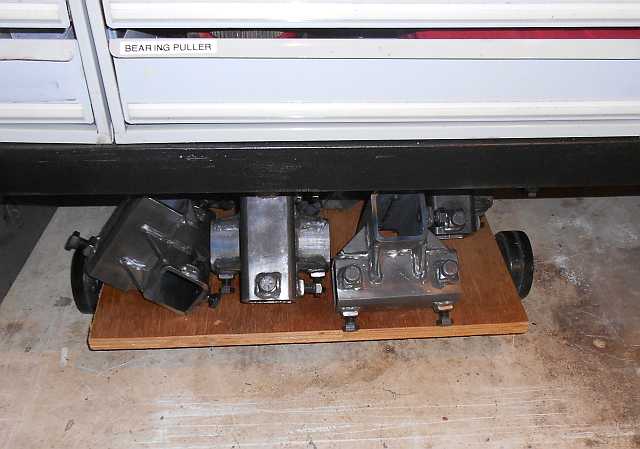
And now it disappears under the workbench! Voila!
And that's the end of this little project. It was fun and useful too.
Thanks for reading!